On Friday evening before attending a lovely gathering with other ITP people playing shuffleboard, I read the basics of Electricity. The “basics” outlined a lot of information. The materials objectively helped a lot, especially the metaphor of an avalanche to explain voltage, current, and resistance (height of mountain/potential energy of event is voltage, amount of snow/rocks is current, steepness of mountain is resistance). Subjectively, I felt a little out of my depth. However, the presence of the pcomp workshop comforted me, knowing more experienced people could guide me in my assembly of the circuits. Thank you to Kay and Sam, in particular for helping me directly, but also Jess and An-Kai for being there.

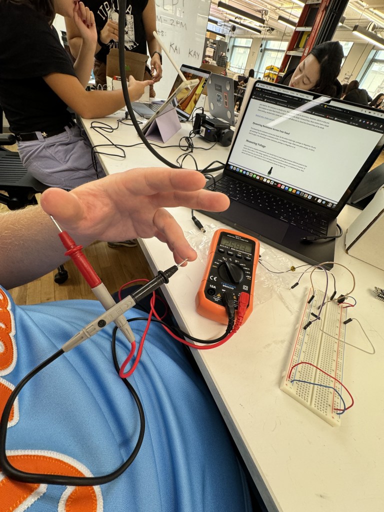
I got lost pretty quickly trying to set up my board and following the lap. After half an hour of squinting and “experimenting” with the public wire stripper (pictured), Sam came to help me. She explained that I had the wrong kind of wires (I had grabbed ones that should be soldered, of course) and showed me where the correct wires were for the breadboard. She also explained that I could use the rainbow bunch given to me in the top right of the photo there.

After a few more minutes, I had the wires set up correctly with a voltage regulator. I was nervous about setting up power for my board and also didn’t know how to. I should have watched the videos given on the website. Luckily, fellow ITP student, Inês, helped me set things up properly with an AC adapter, DC power jack, and the voltage regulator (wire placement: IGO; Input (positive from jack)/Ground (negative from jack)/Output (positive to board column). Thanks to Inês I finally had power running to my breadboard.
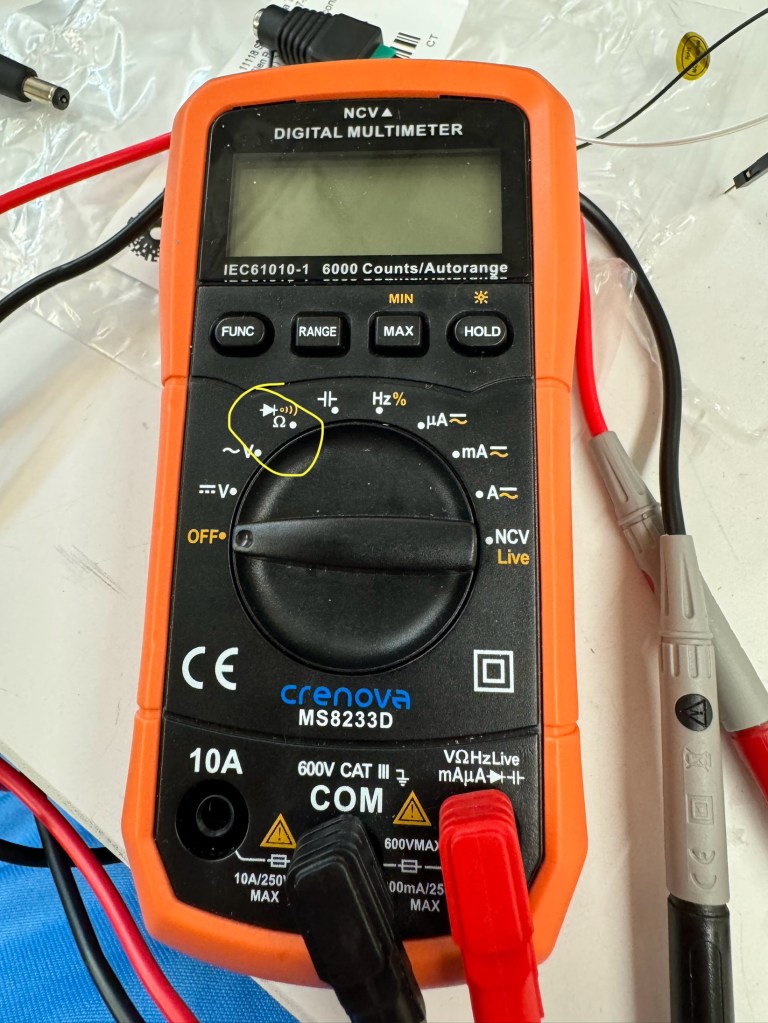
Next, I moved onto the Electronics lab. I tried testing the Multimeter but the ITP one I grabbed did not work (my luck). I asked Kay to help me, just in case I was operating it incorrectly. Kay diagnosed that I was not the issue and lent me their Multimeter, which worked wonderfully. Kay also explained which setting to use for Continuity/Resistance testing on their Multimeter. Thank you, Kay.
With the cumulative help of the residents and fellow students, I finally put together a circuit by myself with a switch and some LEDs in a series.
I didn’t dive too deep into switches, but it is exciting to think the possibilities of interrupting/re-connecting a circuit are limitless. My favorite switch ideas are putting keys in the bowl to close a garage door/vice versa, turning off a light switch by getting into bed, a tv/computer not turning on until I read 10 pages of a book, or shooting a paper ball into a bin revealing a secret door.
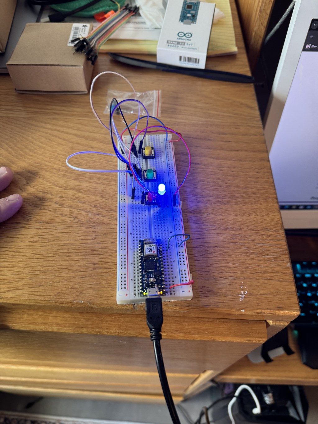
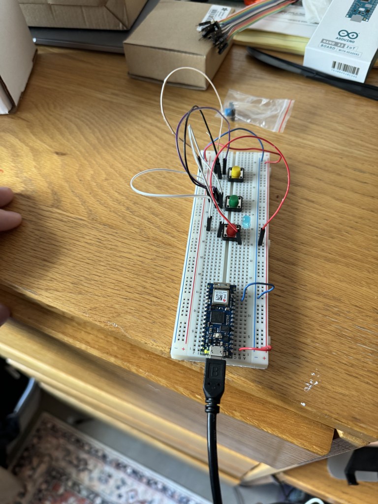
The next day in my apartment, I tried the Switches lab, stopping short of the DC motor example (didn’t have one). I thought I followed the images well in the lab for the three switches in parallel. However, it turns out I had one wire in the wrong place. I can see this being a reoccurring problem in my journey with electronics.
I switched that wire (I believe from positive to negative, if I remember correctly), and voila! Light!

Then, I needed to move the light over a tad. Then, the switches worked beautifully.
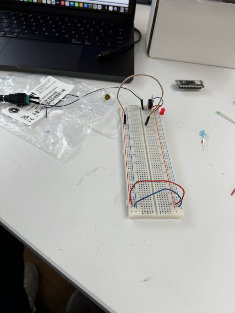
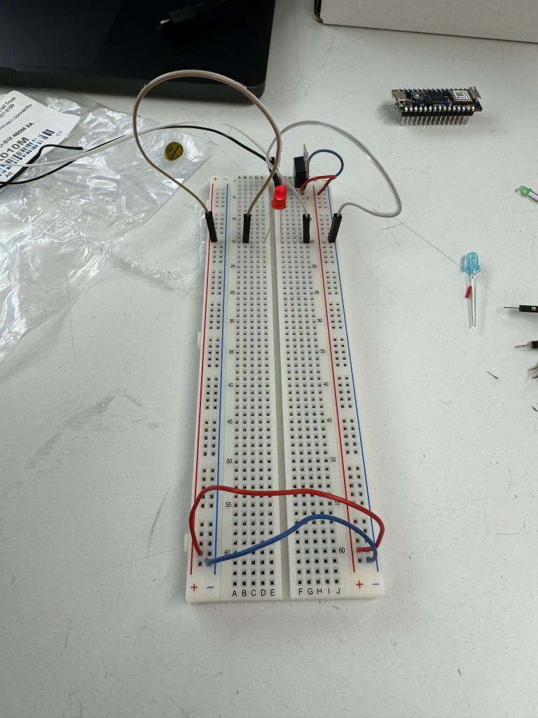
I tried setting up the three switches in a series, but I could not get that to work.
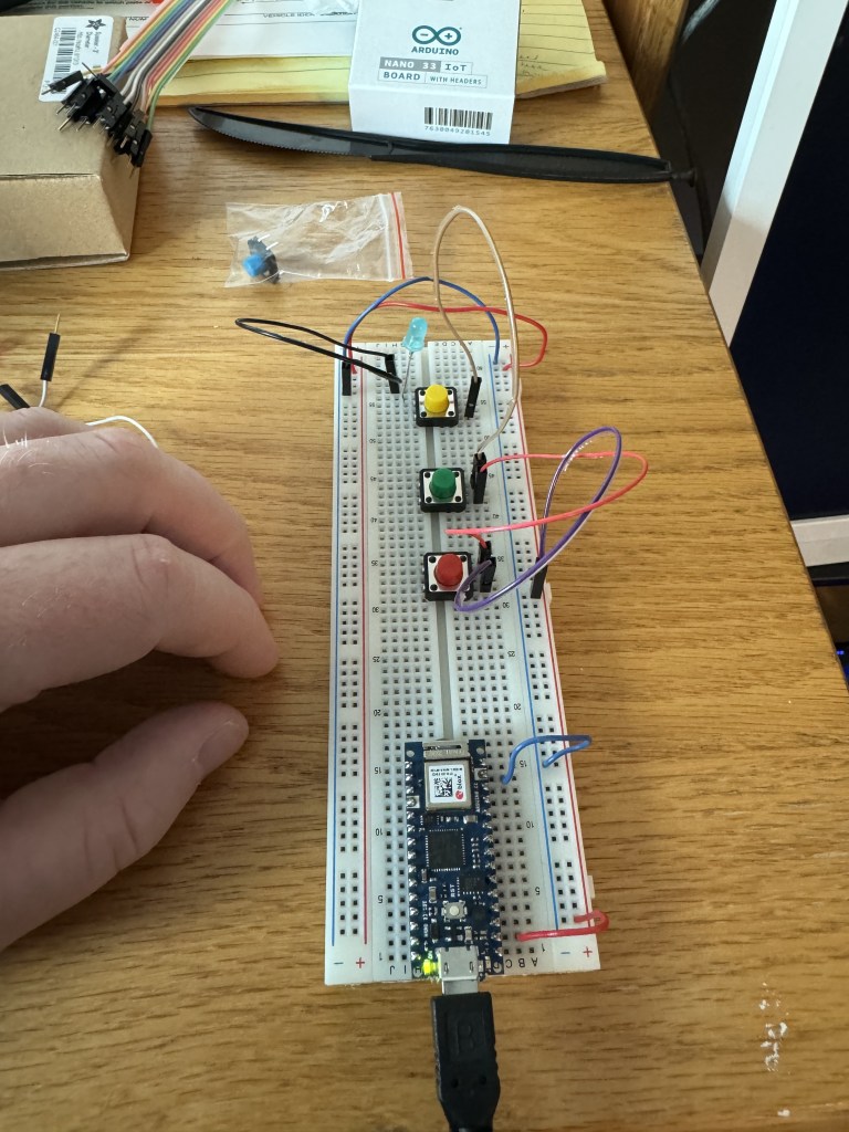
I followed the image on the lab (I think), except for the 220 OHM resistor component. I did not use the resistor since I did not have one at home. Maybe that contributed to my circuit not working. If you notice any visible error I did not catch, please let me know.
Thank you for reading. I cannot wait to see how far the Physical Computing course and my talented collaborators take me.

Leave a comment