Before starting the labs, I read through all of the materials listed above it on https://itp.nyu.edu/physcomp/week-to-week-activity/. What struck me again is just the marvel that computing all works somehow. It continues to be a mystery to me that we can harness electricity and direct it with screens, words, and pins on a little board. How do you even program memory onto something physical with switches? Fortunately, much smarter people have taken care of all that, and I can just worry about which pin/wire goes where (for right now).
Thankfully, I have programming experience so dealing with the Arduino IDE was smooth for me. I’m still getting a grip on the hardware and wiring, but integrating with the code was simple.
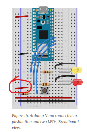
Lab Part 1: Digital Input and Output with an Arduino
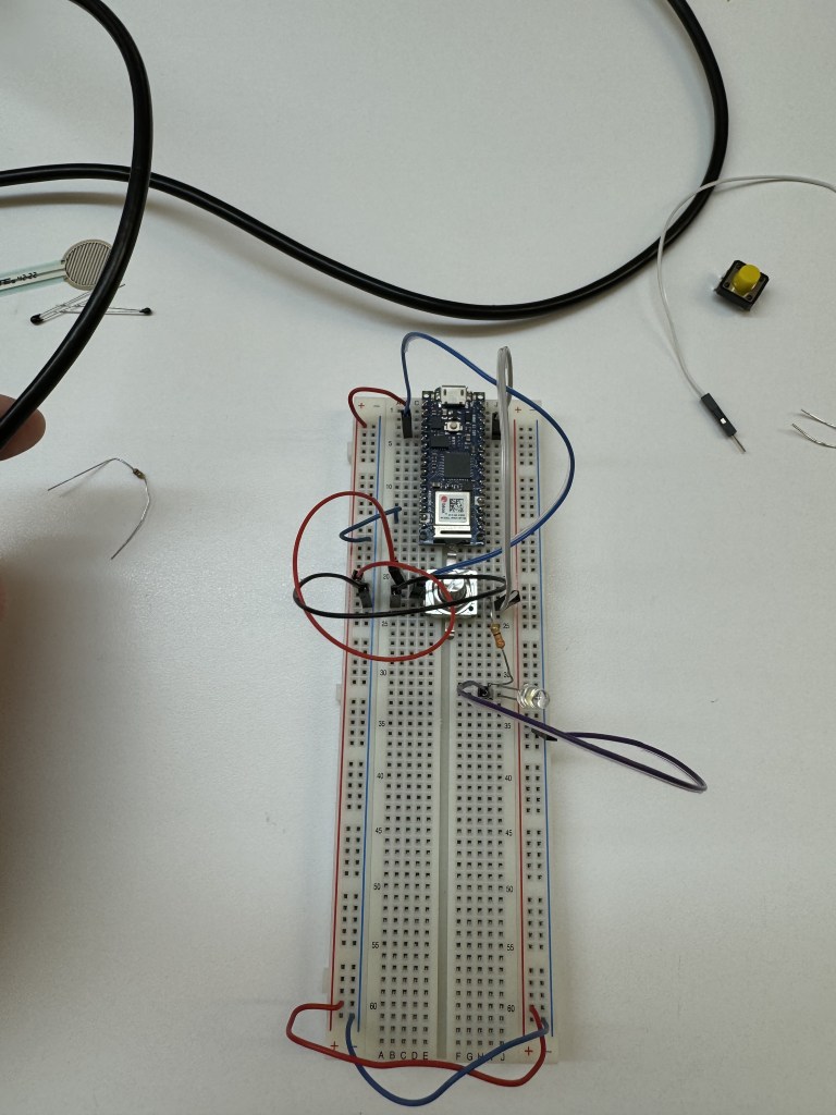
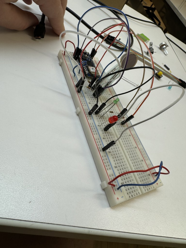
I thought this lab would be very easy, and for the most part, it was. The code setup was straightforward, and the circuit diagram appeared to be straightforward as well. I plugged everything in before plugging in the USB to my computer.
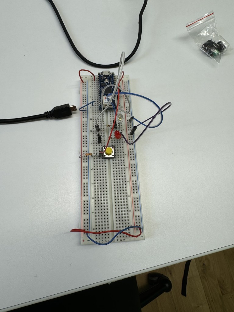

First, I changed out the resistors thinking there was “too much” resistance. I still had not caught my mistake.
Then, I realized I did not upload my code to the Arduino. I had only hit “Verify” so I uploaded it. An LED came on but the switch did not work still.
Finally, I realized I was missing ONE wire that I ignored on the diagram. And the switch and lights all started working perfectly.
Always check the wires. The wires will always humble me.
Code:
part 1 of labs - Digital I/O

 void setup() {
   pinMode(2, INPUT);    // set the pushbutton pin to be an input
   pinMode(3, OUTPUT);   // set the white LED pin to be an output
  pinMode(4, OUTPUT);   // set the blue LED pin to be an output
 }


 void loop(){

   //read the pushbutton input:
   if (digitalRead(2) == HIGH){
     //if the pushbutton is closed:
     digitalWrite(3, HIGH); //turn on
     digitalWrite(4, LOW); //turn off
   }
   else {
     //if the switch is open
     digitalWrite(3, LOW); //turn off
     digitalWrite(4, HIGH); // turn on
   }


 }
Lab, part 2: Analog In with an Arduino
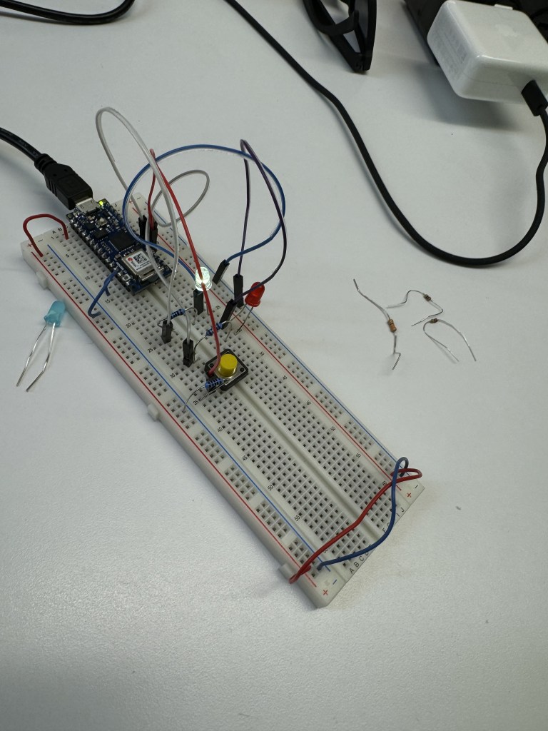
For the first half working with the potentiometer, I plugged in the potentiometer with pins. I do not know if that was intended or if I should have wired the 3 pronged one. In any case, I did get it working with the code and diagram provided.
The code made sense. I had to set up the potentiometer as an analog input in accordance with the corresponding pin on the Arduino. The code then read the potentiometer as an analog input, divided by 4 to fit data into a byte, and then the program logged that current brightness value in Serial.
I played with the potentiometer and saw that it was logging in the program. I realized the potentiometer I used was very sensitive so I played it more and saw the dimming effect a little better. I will have to try the standard potentiometer to see if it will produce a more conventional dimming.
UPDATE: During the PComp help session, I observed someone use the more conventional potentiometer and had plugged it into the breadboard. So I copied them, and it worked much better/cleaner.
For the second half of the lab, I tried in vain to set up the force-sensing resistors with the LEDs. I confirmed that I got the force sensors working by checking the Serial Monitor.

Going off of only a diagram for the Arduino Uno was my main source of difficulty. I could not translate the wires to Nano.
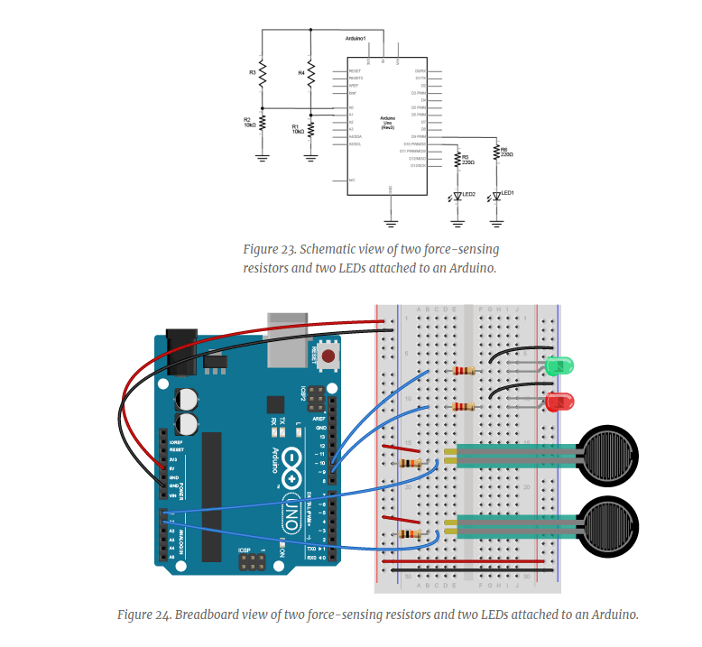
I will go to the PComp help session for more info. Maybe there was something in the code I missed.
UPDATE: I went to the PComp help session and realized I had wired the lights incorrectly. The Uno diagram says to run wire from negative to the LED. I saw my fellow student, Sanaa, and copied her. She had the negative LED leg in the negative bus and that got the light to power on. From there, the sensors affected the lights and logged in the Serial Monitor. Thank you, Sanaa, and thank you to the help session.
Lab, Part 3: Sensor Change Detection
For this part of the lab, everything worked well. I used the button then FSRs again as I was working in the building with other students. I thought the speaker might be too disruptive, but I will need to try that out.
Following along with the code was great. I got the button presses measured in taps, short, and long presses. I had fun with the logging.
Then, using the FSRs, I tested adding more messages based on setting a threshold in the program and logging the peak force being applied.
All in all, I enjoyed this lab and feel like I can start making small things with code and circuits. I cannot wait to do that next week.

Leave a comment