For this week’s lab, I focused on the aspect that served my joint Physical Computing-ICM final project: data collection.
I am working with Trusha Chandan and Rajeshwari Kotel on developing a wearable device that uses proximity detection, audio recording, and machine learning to help remember people’s names after first time social interactions. To acheive this, we are designing a necklace and wristband pairing that will each contain an RFID (to exchange data with another user of said device), listen to conversations and summarize what was discussed and who you talked to, record the data in files and database, and have an OLED screen to show an assistant character (a cat avatar).
It is ambitious, but we are tackling it step by step. For the data collection step, I watched the videos on synchronous serial communication, mainly I2C (Inter-Inter Circuit) and SPI (Serial Peripheral Interface) protocols. The biggest takeaway from me was that SPI was easier with transferring data and that I2C was easier with controlling multiple sensors at once.
For the labs, Trusha decided to focus on Lab: OLED Screen Display using I2C. I focused on Lab: Data Logging With an SD Card Reader using SPI Communication.

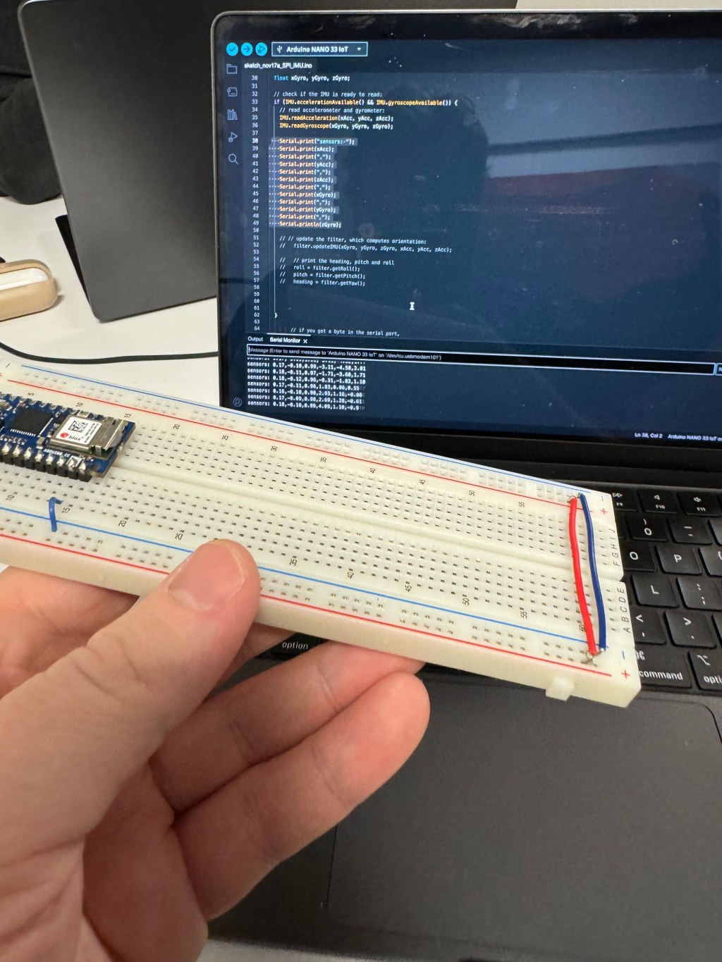
The lab specified to choose a sensor, so I chose the IMU sensor built-in to the NANO 33 IOT board. To access this, I went through part of the IMU lab to get data from the sensor.
Code to access IMU sensor in Nano 33 IOT board

#include "Arduino_LSM6DS3.h"
#include "MadgwickAHRS.h"


//IMU lab: https://itp.nyu.edu/physcomp/labs/lab-serial-imu-output-to-p5-js/

// initialize a Madgwick filter:
Madgwick filter;
// sensor's sample rate is fixed at 104 Hz:
const float sensorRate = 104.00;

// values for orientation:
float roll = 0.0;
float pitch = 0.0;
float heading = 0.0;


void setup() {
  Serial.begin(9600);
  // attempt to start the IMU:
  if (!IMU.begin()) {
    Serial.println("Failed to initialize IMU");
    // stop here if you can't access the IMU:
    while (true);
  }
  // start the filter to run at the sample rate:
filter.begin(sensorRate);
}

void loop() {
  // values for acceleration and rotation:
  float xAcc, yAcc, zAcc;
  float xGyro, yGyro, zGyro;

  // check if the IMU is ready to read:
  if (IMU.accelerationAvailable() && IMU.gyroscopeAvailable()) {
    // read accelerometer and gyrometer:
    IMU.readAcceleration(xAcc, yAcc, zAcc);
    IMU.readGyroscope(xGyro, yGyro, zGyro);

    // Serial.print("sensors: ");
    // Serial.print(xAcc);
    // Serial.print(",");
    // Serial.print(yAcc);
    // Serial.print(",");
    // Serial.print(zAcc);
    // Serial.print(",");
    // Serial.print(xGyro);
    // Serial.print(",");
    // Serial.print(yGyro);
    // Serial.print(",");
    // Serial.println(zGyro);

    // // update the filter, which computes orientation:
      filter.updateIMU(xGyro, yGyro, zGyro, xAcc, yAcc, zAcc);

    //   // print the heading, pitch and roll
      roll = filter.getRoll();
      pitch = filter.getPitch();
      heading = filter.getYaw();

      //   Serial.print(heading);
      // Serial.print(",");
      // Serial.print(pitch);
      // Serial.print(",");
      // Serial.println(roll);


  }

        // if you get a byte in the serial port,
    // send the latest heading, pitch, and roll:
    if (Serial.available()) {
      char input = Serial.read();
      Serial.print(heading);
      Serial.print(",");
      Serial.print(pitch);
      Serial.print(",");
      Serial.println(roll);
    }


}
Eventually, I got it working. Then, I coded the SD card separately at first and then fused the two code sketches.
#include <SPI.h>
#include <SD.h>
#include "Arduino_LSM6DS3.h"
#include "MadgwickAHRS.h"

// the SPI CS pin
const int chipSelect = 10;
const int cardDetect = 9;
// the filename. Use CSV so the result can be opened in a spreadsheet
const char fileName[] = "datalog.csv";
// time of last reading, in ms:
long lastReading = 0;

// initialize a Madgwick filter:
Madgwick filter;
// sensor's sample rate is fixed at 104 Hz:
const float sensorRate = 104.00;

// values for orientation:
float roll = 0.0;
float pitch = 0.0;
float heading = 0.0;


void setup() {

 // attempt to start the IMU:
  if (!IMU.begin()) {
    Serial.println("Failed to initialize IMU");
    // stop here if you can't access the IMU:
    while (true);
  }

  // start the filter to run at the sample rate:
filter.begin(sensorRate);

// variable for the LED's state:
  int ledState = HIGH;
  pinMode(LED_BUILTIN, OUTPUT);
  pinMode(cardDetect, INPUT);


  // if the card detect pin is false, no card:
  while (digitalRead(cardDetect) == LOW) {
    // toggle LED every 1/4 second while the SD card's not present:
    digitalWrite(LED_BUILTIN, HIGH);
  }
  // give the reader 5 seconds to settle the card once it's detected:
  delay(5000);

  // if the card is not present or cannot be initialized:
  while (!SD.begin(chipSelect)) {
    // toggle LED every 1/4 second while the SD card's not responding:
    digitalWrite(LED_BUILTIN, ledState);
    // change the LED state:
    ledState = !ledState;
    delay(250);
  }
  // turn the LED off:
  digitalWrite(LED_BUILTIN, LOW);
}

void loop() {
  // read once a second:
  if (millis() - lastReading > 1000) {

     // values for acceleration and rotation:
  float xAcc, yAcc, zAcc;
  float xGyro, yGyro, zGyro;

  // check if the IMU is ready to read:
  if (IMU.accelerationAvailable() && IMU.gyroscopeAvailable()) {
    // read accelerometer and gyrometer:
    IMU.readAcceleration(xAcc, yAcc, zAcc);
    IMU.readGyroscope(xGyro, yGyro, zGyro);

    // Serial.print("sensors: ");
    // Serial.print(xAcc);
    // Serial.print(",");
    // Serial.print(yAcc);
    // Serial.print(",");
    // Serial.print(zAcc);
    // Serial.print(",");
    // Serial.print(xGyro);
    // Serial.print(",");
    // Serial.print(yGyro);
    // Serial.print(",");
    // Serial.println(zGyro);

    // // update the filter, which computes orientation:
      filter.updateIMU(xGyro, yGyro, zGyro, xAcc, yAcc, zAcc);

    //   // print the heading, pitch and roll
      roll = filter.getRoll();
      pitch = filter.getPitch();
      heading = filter.getYaw();


    // make a string for assembling the data to log:
      String dataString = "";

      // // read your sensors:
      // int sensorOne = analogRead(A0);
      dataString += String(roll);
      delay(1);
      // comma-separate the values:
      dataString += String(",");
      //int sensorTwo = analogRead(A1);
      dataString += String(pitch);

      // comma-separate the values:
      dataString += String(",");
      //int sensorTwo = analogRead(A1);
      dataString += String(heading);

      // comma-separate the values:
      dataString += String(",");
      //int sensorTwo = analogRead(A1);

      dataString += String(millis());


       // open the file. Only one file can be open at a time,
    // so you have to close this one before opening another.
    File dataFile = SD.open(fileName, FILE_WRITE);

    // if the file is available, write to it:
    // turn the LED on while writing and off when not writing too:
    if (dataFile) {
      digitalWrite(LED_BUILTIN, HIGH);
      dataFile.println(dataString);
      dataFile.close();
      digitalWrite(LED_BUILTIN, LOW);
      lastReading = millis();
    } else {
      // if the file can't be opened, leave the LED on:
      digitalWrite(LED_BUILTIN, HIGH);
    }


  }

}

}
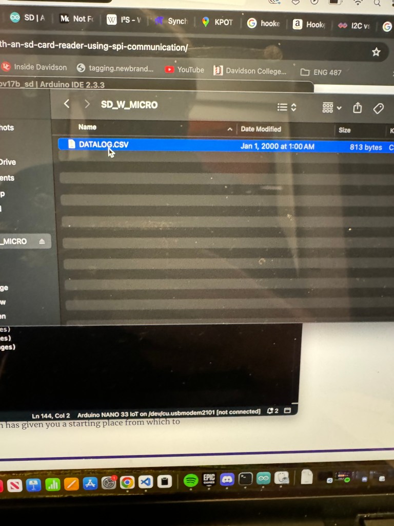
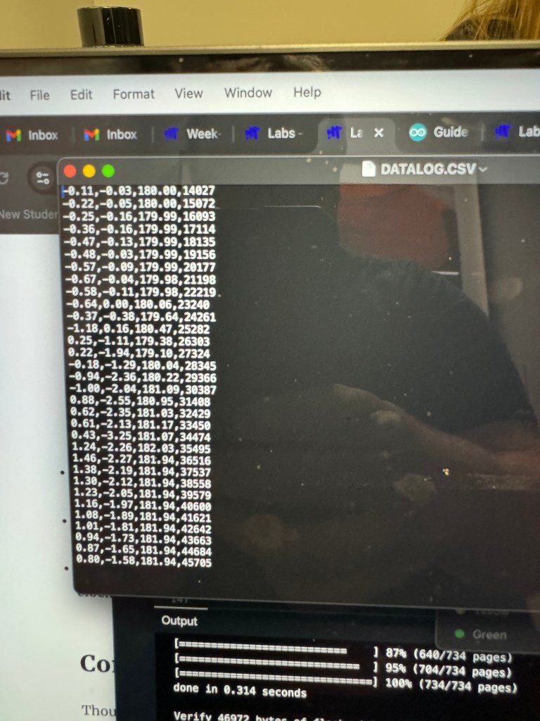
As you can see, I got the initializing part of the code working the micro SD Card reader. The other major part of the lab was reading the data from the sensor and sending it to a “datalog.csv” file defined in the code. I accomplished this with no hassle as the main difficulty was incorporating the IMU data, which proved to be pretty easy as well.
What did prove to be difficult was adding an Electret MAX4466 Microphone Amp (I had to Google that a lot) to the breadboard. I worked on this because our final project will incorporate a microphone in capturing audio data from someone’s conversation. At first, I thought I had wired things incorrectly after following several tutorials because whenever I added the microphone, the entire board would turn off.
After a lot of troubleshooting, re-wiring, and throwing resistors around the board, I realized my soldering of the pins to the microphone board was so sub-par that it was messing up the voltage. I soldered another microphone properly (I understand why all these parts come in packs of 10 now) and finally got it to work.
Going forward, I will be very careful about my soldering and making sure a device can power on properly before I “permanently” attach a component.
Excited for play testing! I wonder how my group’s design will change based on user’s going through the interaction and how “seamless” we intend our data collecting/displaying to be.

Leave a comment