Concept v. Reality

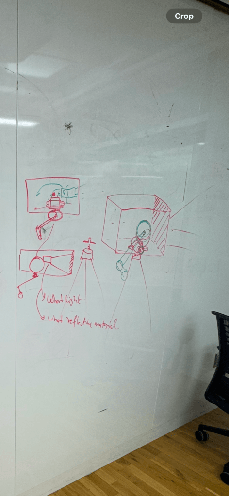
Pictured above are: 1.) our inspiration for our hand-cranked projector, an early 20th century camera that required more physical energy to operate; 2.) our loose design for our projector with electronics encased in a clear acrylic box powered by a hand crank, shooting focused light at a caustic lens, casting an image.
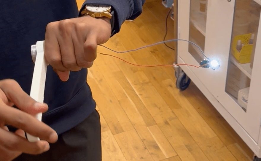
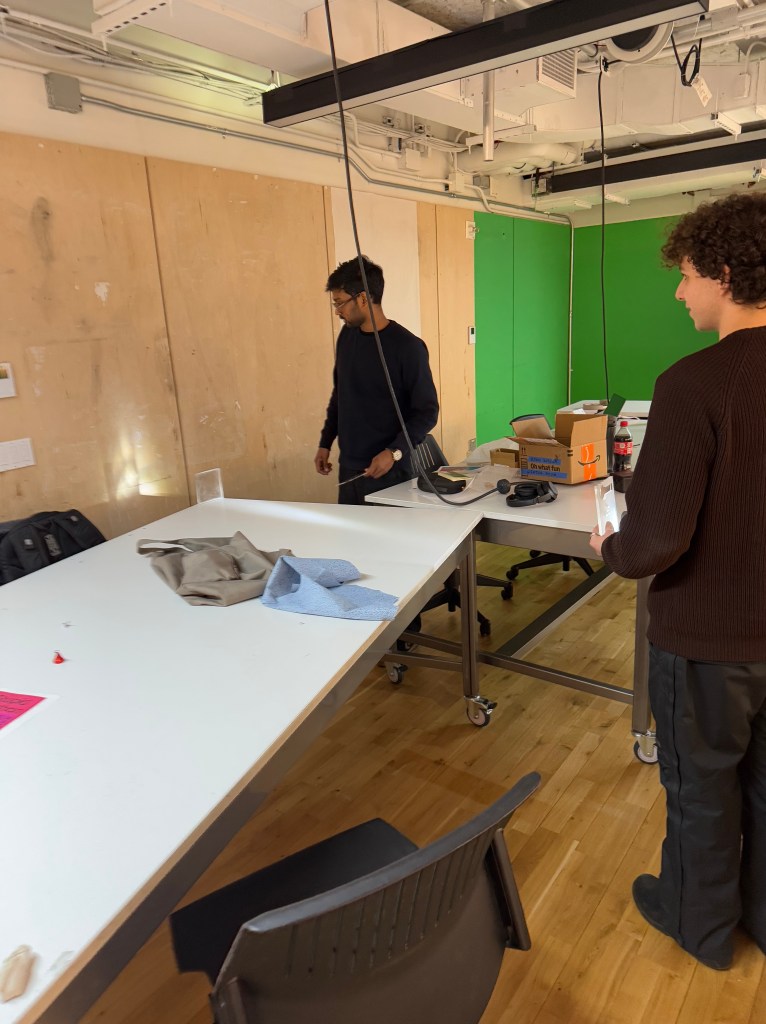
Below is our result:
Obviously, a lot has changed since our idea’s conception and its subsequent birth full of pivots, mechanical design flaws, and too much energy wasted on 3D Printing.
The Journey: From Success to Failure to Ok
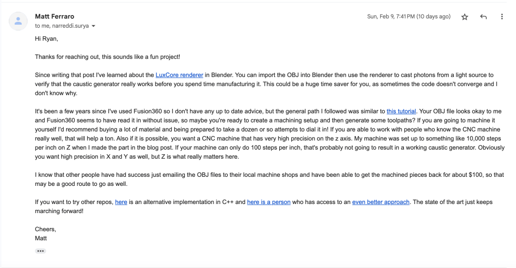
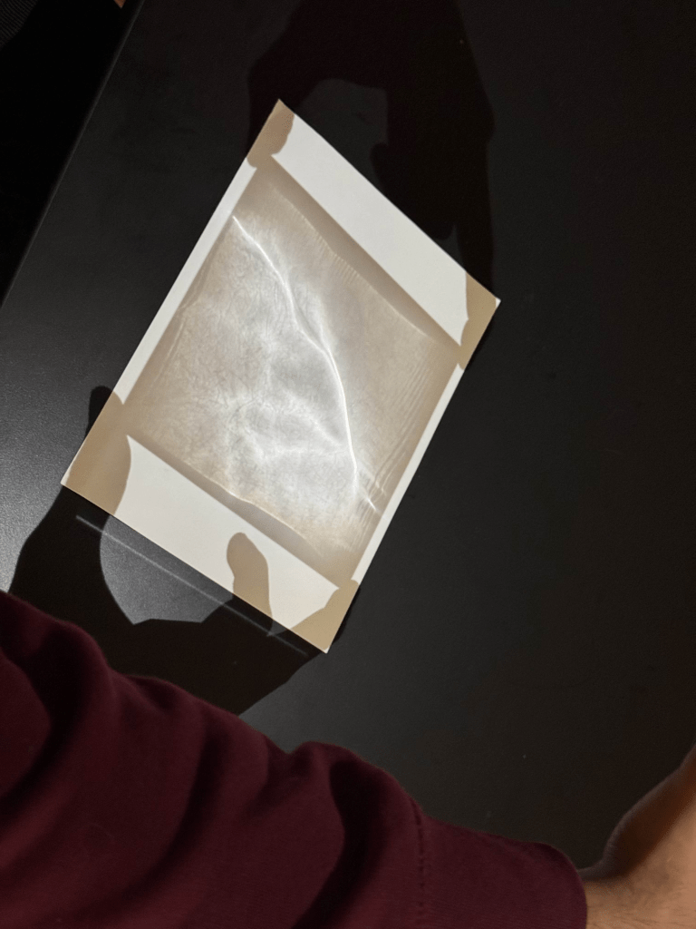
Last week, we had succeeded in CNC-ing an encoded image onto an acrylic lens. A huge thank you again to Matt Ferraro, his blog, and his code for helping us accomplish that. He even responded to our inquiry about more resources and tips with a very prompt and generous response.
And a huge thank you again to Phil Caridi and Ian Cox in the ITP shop for helping us figure out how to design machine cuts in Fusion and actually operating the Bantam CNC machines.
After all that work, Surya and I thought we had figured out the hard part. Putting together the crank and lighting up the bulb would be easy, right?
We were Wrong
Neither Surya (architect/design) nor I (English/IT) hail from a mechanical engineering background. Surya had found a 3D printed crank with an .stl file on Instructables.
Wow, what luck, we thought. But we thought incorrectly.
First of all, the .stl file the author had shared was one big put-together crank that had a bunch of little parts. Printing that design as is would have taken forever on an ITP 3D printer and probably would have got us banned.
But I did notice on his blog that the designer used a software called Prusaslicer to slice all the objects on the design into printable shapes. I decided to use this software myself and sliced up the design into usable objects while also removing all the little problem parts. Which I did, but looking back, I should not have done this.
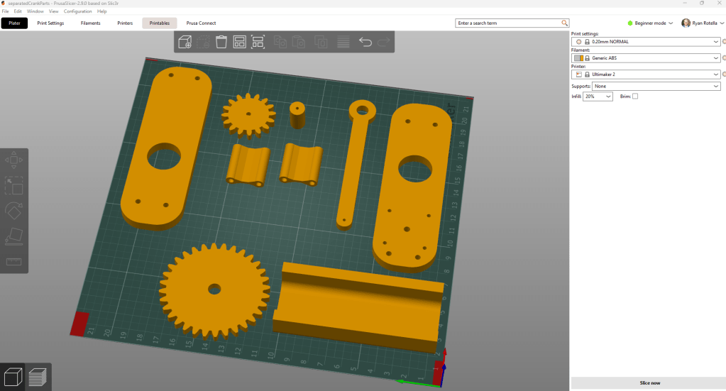
I should not have done this because I then quickly realized a few things. One, these items were not to scale and when I printed these items without adjusting them, all the parts came out tiny.
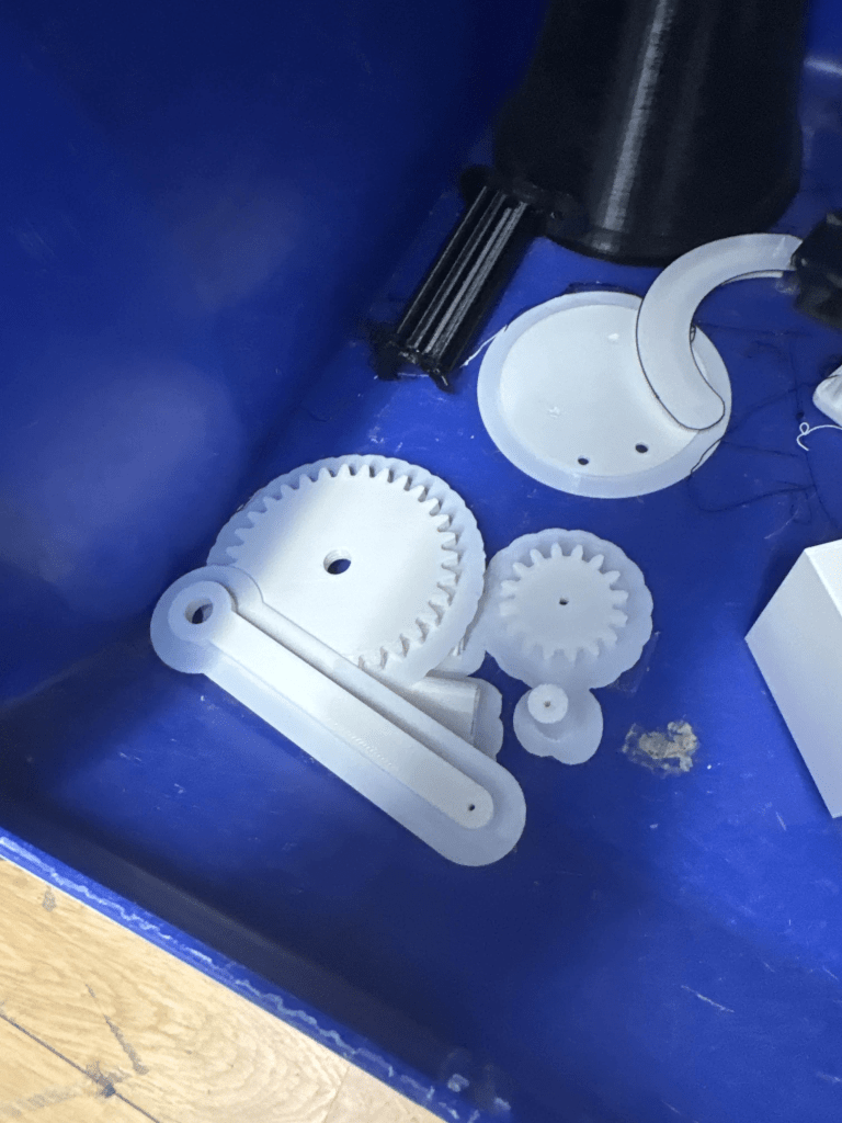
They would not be usable in current condition. We had to scale them up, which required a lot of guessing within 3DPrinterOS in terms of lining things up with our parts. We wasted a lot of time doing trial and error before we remembered to measure these components with our actual motor and whatever we were using for our axle and screws. And we were printing the whole 3D print, not just a sample of the hole. Being rookies in anything means failing but we underestimated dealing with problems in 3D, even as Jeff told us to think those through more.

After failing to print a gear that fit our DC motor and eventually understanding Fusion more and more, we reached out to our friend and fellow ITP student, Fabri, to help us figure out this 3D and fabrication nonsense.

He then suggested using the laser cutter and cutting acrylic based on an exact sketch drawn in Adobe Illustrator. We could draw a sketch in Fusion, export that as .dxf file, import it to Illustrator, and laser cut the exact dimensions, no more guessing and praying to the 3D printer gods.
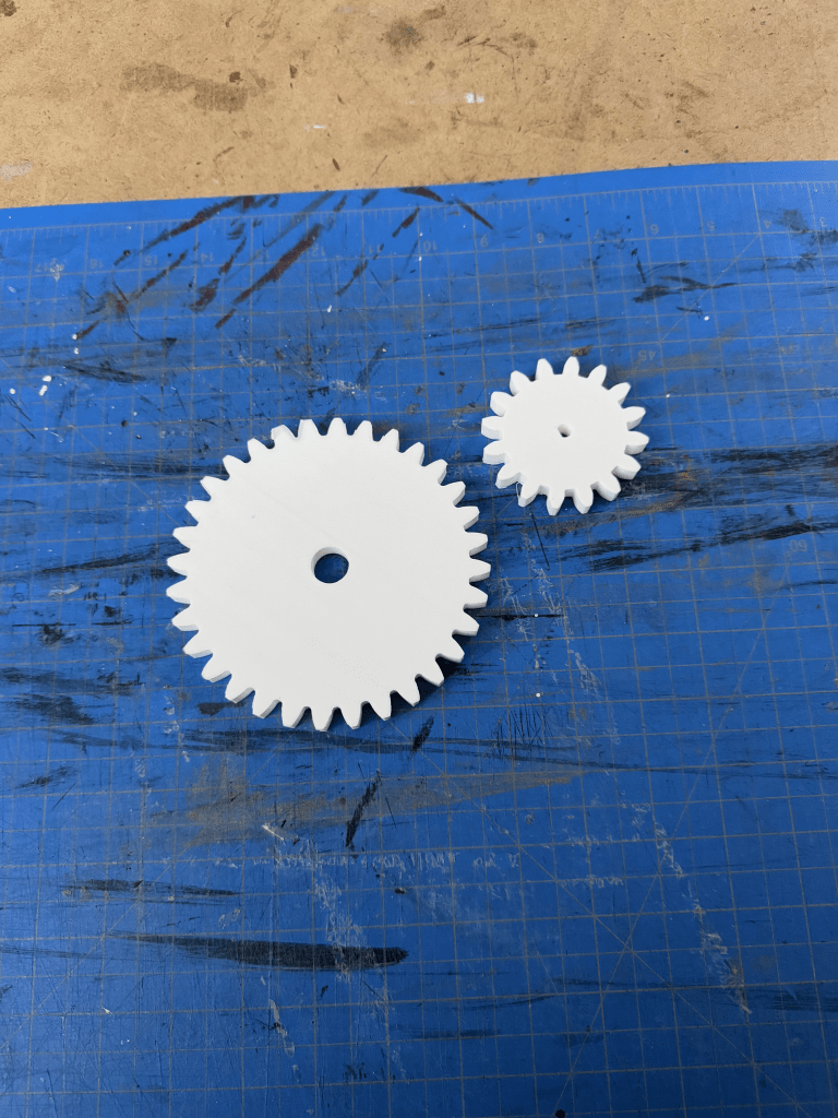
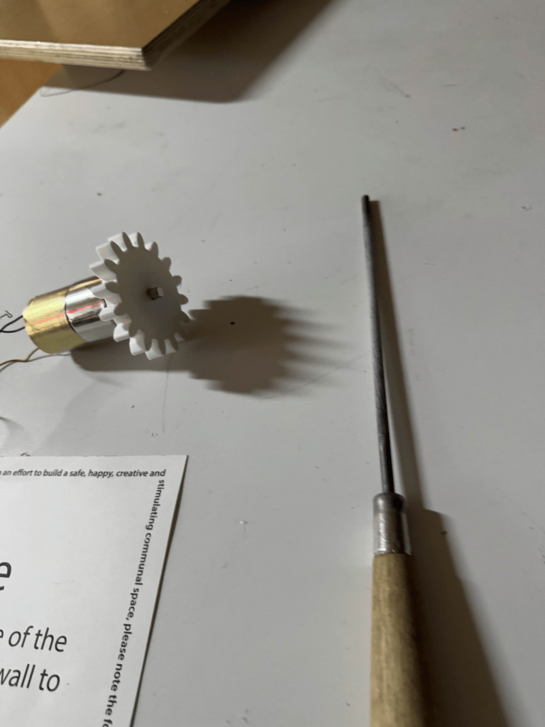
With this method, we produced a perfect small gear for our motor.
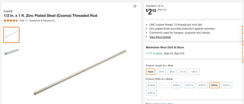
Even though we figured out the laser printer was better, we still opted to 3D print the big gear and casing sides. This was fine for the big gear because it was going around a threaded rod and nuts/washers I acquired at Home Depot, thanks to the guidance of a kind worker there named Kirill.
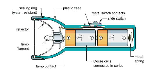
Electronically, everything was smooth sailing. We disassembled the flashlight, and we were quickly able to figure out how to complete a circuit for the blub and metallic rim around it.
In 3D world, we did figure out a working big gear with an axle, little gear that fit our motor, and supports we could bolts through.
However, the side cases we 3D printed could not contain our project properly. There were too many new elements of nuts and bolts to adjust our design for 3d printing, and the cases needed to be thick and therefore could not be laser cut from thinner material like our gears.
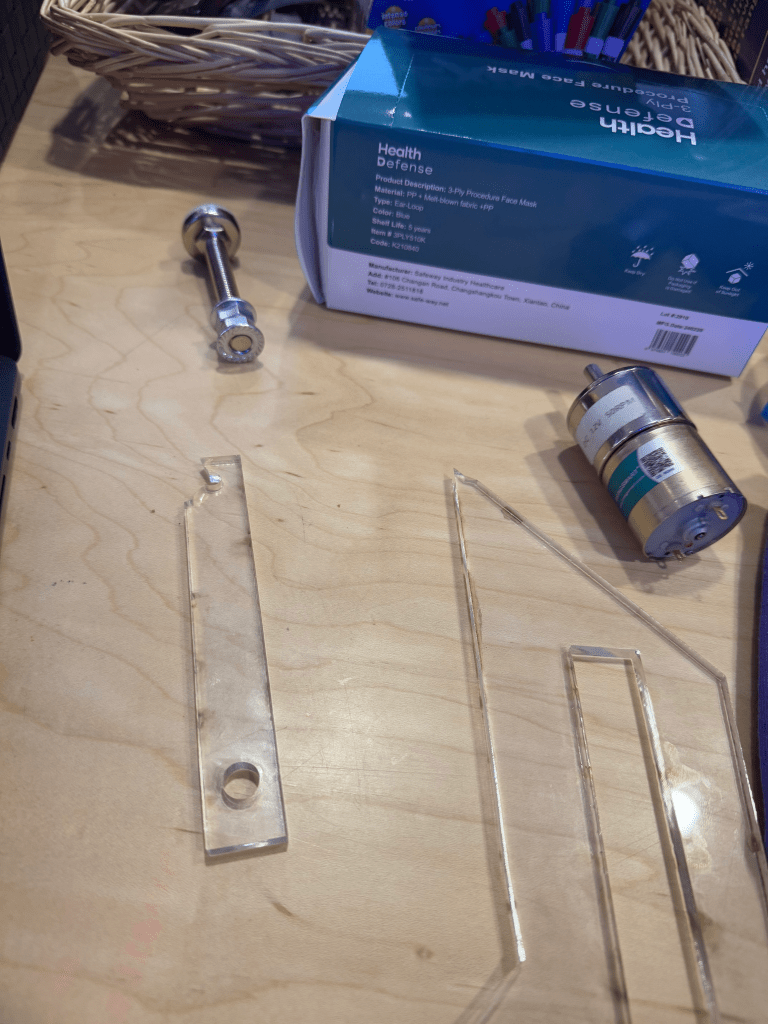
Instead, we pivoted to having a crank with a lower hole that fits in our DC motor and the upper hole containing a bolt secured with nuts on either side as a handle.
Currently, we’re working to 3D print the handle (the acrylic we’ve laser cut has snapped), wire the motor and light together (quick soldering, probably need a good resistor, possible rectifier circuit), and secure everything, including our lens (our crown jewel), to a wooden base.
Update
We found a spare 3D printed handle (out of one of our many failures) and secured that around this handwheel I had this whole time.

We didn’t have enough time to add a rectifier circuit or a base. Hopefully, we can refine this project and make the box we originally wanted. For now, Surya and I walk away from this project with a much better appreciation of how much work it takes to get a little energy. We live in an era where we are spoiled with plentiful and excessive energy that we have to do zero personal, physical work for.
I also appreciate the engineers and scientists who know so much that I do not. We are truly living off the shoulders of giants in all that we do.
Also: never use plastic or acrylic to turn a motor.

Leave a comment